I have been playing my flute quite regularly in preparation for my grade 6. I came up with this initial idea during lockdown when I was playing flute to my grandma. She told me that she wished that she could play the flute but is unable to, because of her arthritis. I then had the idea that I would try and help her.
Microcontroller research
A micro controller is an integrated circuit that is programmed to do a specific task. It is designed to do a specific task in an embedded system. They control small sections of larger components. Microcontrollers are sometimes called ‘mini computers’, ‘embedded controllers’ or ‘MCU (micro controller unit). It only requires a clock speed of a few MHz. Micro controllers only work when they are coded to do something. A micro controller was named this way because it has an execution time of a few microseconds or sometimes a few seconds.
SOURCES – powerpoint from solid state workshop: What is a Microcontroller and How Does it Work? (techtarget.com) What is a Microcontroller and How Does it Work? (techtarget.com)
Coding for microcontrollers
Code is written for microcontrollers in Integrated Development Environments (IDEs). For example, a computer program that uses one of the following programming languages: C, BASIC or assembly. The IDE debugs the program for errors and then converts it into binary so that the microcontroller can execute it. A program downloader can then be used to transfer code from the host computer to the microcontroller. The most common type of program downloader is an “in circuit serial”.
Source: powerpoint from solid state workshop
Where are microcontrollers used?
-Automation
-Robotics
-IoT devices and systems
-Handheld diagnostic devices
-Xray machines
-Navigation software
Source https://uk.rs-online.com/web/generalDisplay.html?id=ideas-and-advice/microcontrollers-guide
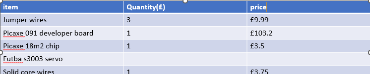
Items Required
I decided to use an AXE091 development board because I have used it recently to make a train level crossing project. I have also used picaxe boards for an electronic dice. I found picaxe development boards to be efficient and easy too use.
I selected the futba s3003 servos because I previously used them to drive the gates for the train level crossing system and they worked very well.
I also needed to use some solid core wires to attach the microcontroller to the breadboard.
For my microcontroller, I decided to use the PICAXE-18M2 chip because it is compatible with my picaxe board and has enough pins for me to add 8 servos. It also has enough pins for me to add any extra functionality without too much additional expense
Items price list
youtube channel
I decided to create a youtube channel to document this project and other stem projects that I am working on
https://www.youtube.com/channel/UCewKRWYfWVmMWQEvkUKfXsg/
Wiring
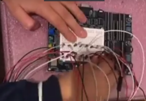
When I first wired up my servos, I connected them the wrong way round (I thought that the top row in the breadboard was +v!)
See my wiring youtube video below
Cables and breadboards
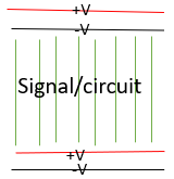
I used the following colour coding for my cabling:
•Red +V
•Black 0V
•White Signal (shown as green on the diagram)
Connecting the breadboard to the 18M2 chip
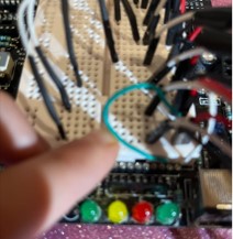
When I tried to connect the breadboard to the chip, the heads of the jumper wires did not fit, so I had to get some solid core wire and remove the head of the jumper wire and then attach them together (see the video below)
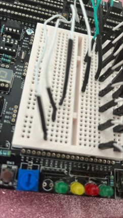
In the video, I also joined together some wires (using either cable ties or insulation tape) to prevent tangling. When I had wired up some of the new connections, I realized that the solid core wire was too thin and it slipped out of the chips hole. Therefore, I ordered some thicker wire and redone some of wiring
In the above video, I also connected some of the wires together. I also used green
wires for the left hand and white for the right hand in order to make any errors easier too
spot
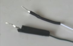
I also found that the new wire attachments were better quality because
they used shrink wrap instead of tape to attach the head. I found that shrink wrap was better (the insulation tape kept falling off!)
Music

Programming plan
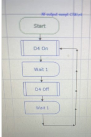
For the programming, I decided that it would be easiest to code in flowcharts as I already know how to code that way. I find flowcharts much simpler than blockly, because it is more straightforward to create subroutines and program them to do what I need.
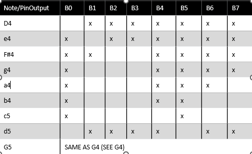
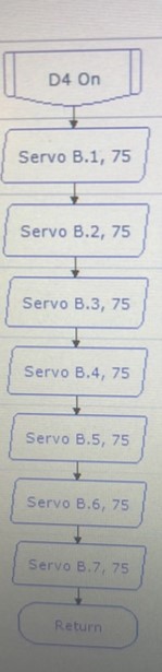
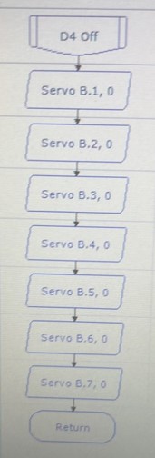
I decided it would be simplest to create subroutines to move each servo to the playing position and then another for the servo to move down to non playing position for each note. I can then use the wait command for the note to be played for the amount of time required.
Programming – Part 1
I downloaded PICAXE developer 6 onto my computer. When I tried to test the servos, I realised that they needed to be attached to the B pins (and not the C pins). Therefore, I had to re-draw my circuit diagram, otherwise the servos would not move.
Updated circuit diagram
To be uploaded
Programming adjustments
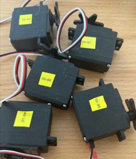
During programming, I decided to add labels to my servos on each side so that I could tell which servo was moving in order to verify my code. I used the following labelling convention: s meaning the servo and the number which it is allocated to it and then ‘-‘ for the pin number.
Test program
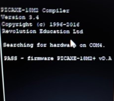
I initially ran into a problem because I could not refresh the com ports to allow the data to be uploaded to the axe 027 development board. I read the axe 027’s specification and discovered that I needed to install BOTH the axe027’s USB driver and the serial driver.
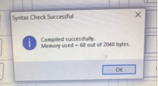
I first tested the part of the program which plays the 1st bar. I also ran a syntax check
Test program
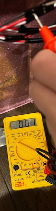
When I ran my program using the PICAXE simulator, it are was all working. However, when I downloaded the program to the target, the servos were not moving. I decided it must be a hardware issue, so I changed my code to use only one servo. I then used a multi-meter too see check the voltages. I then watched a few youtube videos on the axe091 developer board, where I found out that I needed to connect a cable to the the +V and 0V from the PCB to the breadboard. Once I did this, I repeated the multimeter check and confirmed that the voltages were at the expected levels
Test program
I then tested to see how many servos could run at once by adding one servo at a time. Checking the power drain: With four servos it runs fine, but with five servos the motors sound laboured. With six servos they still work, but are even louder and with seven servos, they are all just about working. At one point, I accidentally wired up one of the servos incorrectly (reverse polarity) and they all stopped working!
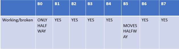
I then looked through my code and realised that I did not code B0! I added support for B0 into my code but it still did not move properly. When I held the B0 servo in my hand, I could feel it pulsing. I then replaced the servo on pin B0 and although it now works, it is still not moving the amount required.